NEWS & EVENTS
A Comprehensive Guide to Verifying the Rationality of Reflow Soldering Fixture Design and Conducting Necessary Tests

Learn how to verify the rationality of reflow soldering fixture design and the necessary tests. Understand the importance of design verification for production efficiency, product quality, and cost control. Discover key elements and test items to ensure high - quality soldering in electronics manufacturing.
Overview of Reflow Soldering Fixtures
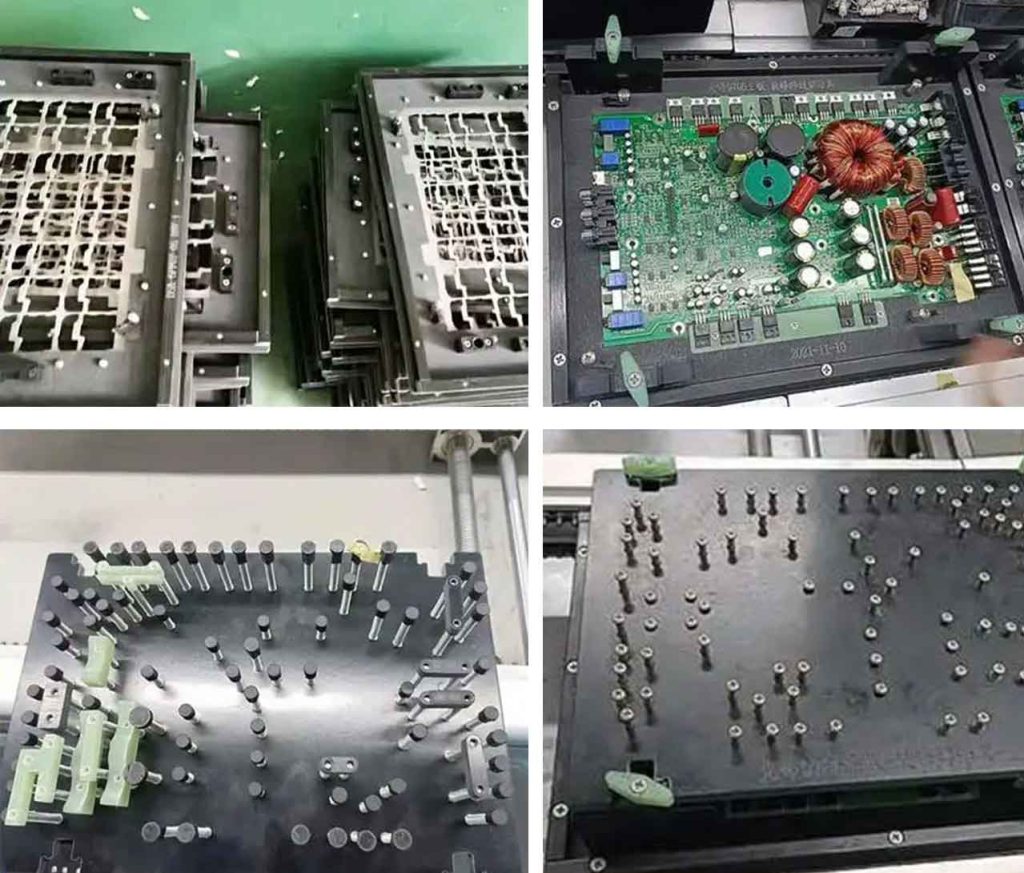
Reflow soldering fixtures are specialized tools used in the electronics manufacturing industry. Their main function is to hold printed circuit boards (PCBs) and electronic components in place during the reflow soldering process, ensuring accurate and stable soldering. Common types of reflow soldering fixtures include carrier fixtures, pallet fixtures, and custom – designed fixtures for specific products. In today’s electronics manufacturing, with the continuous miniaturization and high – density integration of electronic products, the demand for high – quality reflow soldering fixtures is increasing. They play a crucial role in mass – production lines, improving the efficiency and quality of soldering operations.
Importance of Verifying Design Rationality
Impact on Production Efficiency
A reasonably designed reflow soldering fixture can significantly enhance production efficiency. For example, in a large – scale mobile phone PCB production line, a well – designed fixture can reduce the time required for loading and unloading PCBs. A traditional fixture might take 10 seconds per PCB loading, while an optimized fixture can cut this time down to 5 seconds. This reduction in time per unit accumulates over a large production volume, leading to a substantial increase in the number of products that can be processed per hour. Moreover, a good fixture design can also improve the flow of the production line, reducing bottlenecks and increasing the overall throughput.
Assurance of Product Quality
A properly designed fixture is essential for ensuring product quality. When soldering PCBs, if the fixture cannot firmly hold the PCB and components, it may cause the PCB to deform during the high – temperature reflow process. This deformation can lead to problems such as uneven solder joints, including issues like insufficient solder (cold solder joints) or excessive solder (bridging). For instance, in a high – end computer motherboard production, a well – designed fixture can prevent the PCB from warping, ensuring that all components are soldered in the correct position and with the right amount of solder, thus reducing the defect rate and improving the reliability of the final product.
Significance for Cost Control
A rationally designed reflow soldering fixture can effectively control costs. Firstly, it can reduce material waste. If a fixture is not well – designed, it may cause misalignment during soldering, resulting in the need to rework or scrap PCBs. By using a well – designed fixture, the number of defective products can be minimized, saving on the cost of raw materials and labor for rework. Secondly, it can also reduce the maintenance cost of soldering equipment. A fixture that fits well and functions properly puts less stress on the soldering machine, reducing the frequency of breakdowns and the need for maintenance.
Key Elements for Verifying Design Rationality
Rationality of Structural Design
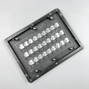
The overall structure of the reflow soldering fixture should be stable and reasonable. It needs to be able to firmly fix the PCB and electronic components during the soldering process. For example, the clamping mechanism of the fixture should be designed in such a way that it can evenly distribute the clamping force across the PCB, preventing it from moving or vibrating. At the same time, the structure should also be easy to operate. Workers should be able to quickly load and unload PCBs without much effort. In addition, the fixture should be easy to maintain, with accessible parts for cleaning, lubrication, and replacement.
Suitability of Material Selection
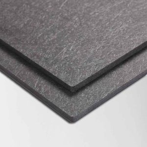
The choice of fixture materials should meet the requirements of the soldering process. The materials need to have properties such as high – temperature resistance, anti – static, and low thermal conductivity. Here is a comparison of different materials:
| Material | High – Temperature Resistance | Anti – Static | Low Thermal Conductivity | Advantages | Disadvantages |
|---|---|---|---|---|---|
| Aluminum Alloy | Good, can withstand high – temperature soldering environments | Can be treated to be anti – static | Relatively low thermal conductivity | Lightweight, easy to process | May oxidize over time |
| Ceramic | Excellent high – temperature resistance | Naturally anti – static | Low thermal conductivity | High durability | Brittle, difficult to process |
| High – Temperature Plastic | Can withstand certain high – temperature ranges | Can be made anti – static | Low thermal conductivity | Low cost, easy to mold | May deform at extremely high temperatures |
Accuracy of Dimensional Precision
The dimensional precision of the fixture is of great importance. It must match the dimensions of the PCB and electronic components. Any dimensional deviation can lead to soldering problems. For example, if the holes in the fixture for component placement are slightly larger than the actual components, the components may not be properly seated, resulting in poor solder joints. On the other hand, if the holes are too small, it may be difficult to insert the components, or it may even damage the components during the insertion process. Therefore, strict control of dimensional precision is necessary to ensure the quality of soldering.
Test Items for Reflow Soldering Fixtures
Temperature Uniformity Test
The temperature uniformity test is crucial for reflow soldering fixtures. According to international mainstream real – board testing and soldering test control performance standards, the temperature across the fixture should be as uniform as possible during the soldering process. Non – uniform temperature can lead to various soldering defects. For example, if one area of the PCB is at a much higher temperature than another, the solder in that area may melt too quickly, causing bridging, while in the cooler area, the solder may not melt properly, resulting in cold solder joints. To conduct this test, thermocouples are usually placed at multiple points on the fixture and the PCB. The temperature data is then collected and analyzed to ensure that the temperature difference within the soldering area is within an acceptable range.
Heat Transfer Efficiency Test
The purpose of the heat transfer efficiency test is to evaluate the heat transfer performance of the fixture during the soldering process. A good fixture should be able to transfer heat efficiently to the PCB and components, ensuring that the soldering area reaches the required temperature quickly and stably. If the heat transfer efficiency is low, it may take longer for the solder to melt, increasing the soldering time and potentially affecting the quality of the solder joints. To measure heat transfer efficiency, the temperature change over time at different points on the fixture and PCB is monitored. The rate of temperature increase and the time required to reach the soldering temperature are important indicators for evaluating heat transfer efficiency.
Sealing Test
The sealing test is very important for reflow soldering fixtures. A well – sealed fixture can prevent problems such as re – melting of solder points and virtual soldering. During the soldering process, if the fixture is not properly sealed, hot air or solder fumes may escape, which can lead to uneven heating and contamination of the soldering area. To test the sealing performance, methods such as pressure testing or using smoke to detect leaks can be employed. If there are any leaks, it indicates that the fixture’s sealing design needs to be improved.
Positioning Accuracy Test
The positioning accuracy test is necessary to ensure that the fixture can accurately position the PCB and electronic components. Precise positioning is crucial for the correct placement of components and the formation of high – quality solder joints. If the positioning is inaccurate, components may be soldered in the wrong position, leading to electrical connection problems and product malfunctions. To conduct this test, precision measuring tools such as coordinate measuring machines can be used to measure the actual position of the components on the fixture – held PCB and compare it with the designed position. Any deviation should be within the specified tolerance range.
Analysis of Test Results and Improvement
Evaluation of Test Data
The test data needs to be carefully analyzed to determine whether the fixture design is reasonable. By comparing the test results with the pre – set standards and requirements, we can identify any problems and deficiencies in the design. For example, if the temperature uniformity test shows a large temperature difference across the fixture, it indicates that the heat distribution design of the fixture may be flawed. If the positioning accuracy test reveals significant deviations, the positioning mechanism of the fixture needs to be re – evaluated.
Formulation of Improvement Measures
Based on the test results, corresponding improvement measures should be formulated. If the structure design is found to be the cause of the problem, adjustments such as modifying the clamping mechanism or adding reinforcement structures can be made. If the material selection is not suitable, a more appropriate material can be chosen. For example, if the fixture is found to deform at high temperatures, a material with better high – temperature resistance can be used. If the dimensional precision is off, the manufacturing process needs to be optimized to improve the accuracy of the dimensions.
Re – testing for Verification
After the improvement measures are implemented, the fixture needs to be re – tested to verify the effectiveness of the improvements. This re – testing ensures that the fixture design meets the requirements. If the re – test results still do not meet the standards, further analysis and improvement are required until the fixture can perform its function effectively in the reflow soldering process.
Share this article:
Recent Posts
Process Differences and the Necessity of Tooling in Wave Soldering vs. Reflow Soldering
While Wave Soldering and Reflow Soldering are the twin pillars of PCB assembly, they require vastly different strategies to ensure quality.
Official Notice: Product Price Adjustment
Due to the impact of global instability and the appreciation of the RMB, raw material costs in China have risen significantly.
High-Performance PCB Solder Pallet & Fixture Material
Our PCB Solder Pallet Material is a game-changer for wave soldering—offering extreme thermal stability, ESD protection, and 20,000+ cycle durability.
Leave a message
* Thank you for visiting our website. We hope you found the information you were seeking.
* If you have any questions about our products, pricing, or would like to schedule a consultation, please contact us.